Multi PIC Programmer 5 Ver.2
 |
| I built a "Multi PIC Programmer 5 Ver.2" based on the"JDM Programmer." |
|
| I built a "Multi PIC Programmer 5 Ver.2" based on the"JDM Programmer." |
[Home]
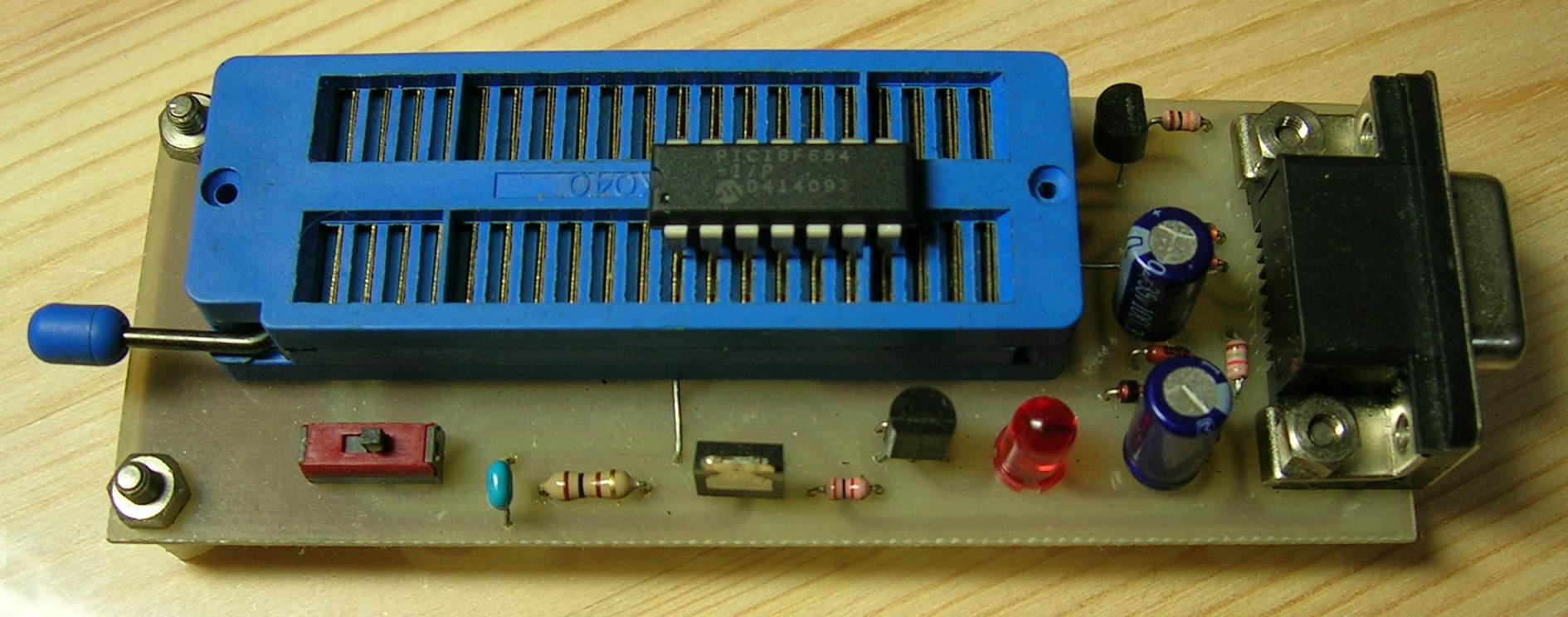
"Multi PIC Programmer 5 Ver.2" is a PIC programmer, which can program to 8-pin to 40-pin devices using single ZIF socket.
I built "Multi PIC programmer 5 Ver.1", in order to enable it to program 40-pin devices like PIC16F877 with a ZIF socket.
Lately I improved this PIC programmer. The main improvements are having made it suit "VPP before VDD" and changed wiring of a ZIF socket for accepting devices with LVP (Low Voltage Programming) mode.
Before you build this "PIC programmer", I recommend checking to see if there is enough output voltage at the serial port your personal computer. If TxD, DTR, and RTS do not have more than +7.5V(or -7.5V), this programmer will not work well, especially, with the latest laptop computers that using low power RS232 interface ICs.
Other important matters are as:
1. The GND line of a serial port forms relative VDD on a PIC programmer. All the GND symbols in a circuit diagram are a PIC programmer's GND. Never connect them with GND line of a serial port.
2. This PIC programmer changes VPP in accordance with the device selected (8-18pin) or (28-40pin) with one sliding switch. So, if the insertion position of a device and slide switch is not set correctly, your PIC may be damaged by over voltage.
3. This PIC programmer does not support all PIC MCUs. (PIC16C5x is not programmable with this programmer. By using an adapter, the 20 pin PIC 16C770/771 can be programmed.
4. I did not try all PICs since and I do not have all them. The PICs, which I successfully programmed and verified, are PIC12F629, PIC12F675, PIC16F627, PIC16F628, PIC16F630, PIC16F676, PIC16F818, PIC16F819, PIC16F84A, PIC16F873, PIC16F877A, PIC18F2320, PIC18F452.
5. The programming software used is IC-Prog of Bonny Gijzen.
6. "Hardware settings" of IC-Prog are the same as the JDM programmer.
I am publishing this circuit diagram and the PCB for the first times for the benefit my friends in of India. So, this circuit diagram and the PCB can be downloaded from the site of Ham Radio India.
Supported and tested devices list (added: 2005-02-06 JST)
- PIC12C508,PIC12C509
- PIC12C508A,PIC12C509A
- PIC12CE518,PIC12CE519
- PIC12C671,PIC12C672,PIC12CE673,PIC12CE674
- PIC12F508,PIC12F509 The trick of programming PIC12F508/509 using IC-Prog
- PIC12F629,PIC12F635(1)(2),PIC12F675,PIC12F683(2)
- PIC16C505
- PIC16C61,PIC16C62A,16C62B(3),PIC16C63,PIC16C63A
- PIC16C64A,PIC16C65A,PIC16C65B,PIC16C66,PIC16C67
- PIC16C620,PIC16C620A,PIC16C621,PIC16C621A,PIC16C622,PIC16C622A
- PIC16CE623,PIC16CE624,PIC16C625
- PIC16F627,PIC16F628
- PIC16F627A(2),PIC16F628A,PIC16F648A
- PIC16F630,PIC16F636(2),PIC16F676,PIC16F684(2),PIC16F688(2)
- PIC16C710,PIC16C711(3),
PIC16C715(6)- PIC16C712,PIC16C716(3)
- PICPIC16C71,PIC16C72,PIC16C72A,PIC16C73A,PIC16C73B,PIC16C74A,PIC16C74B,PIC16C76,PIC16C77
- PIC16F72,PIC16F73,PIC16F74,PIC16F76,PIC16F77
- PIC16C745(3),PIC16C765(3)
- PIC16C717,PIC16C770,PIC16C771(7)
- PIC16C773,PIC16C774
- PIC16C781(7),PIC16C782
- PIC16C923,PIC16C924
- PIC16F818,PIC16F819
- PIC16F83
- PIC16C84
- PIC16F84
- PIC16F84A
- PIC16F87(2),PIC16F88
- PIC16F870(8),PIC16F871(8),PIC16F872,PIC16F873,PIC16F874(4),PIC16F876(5),PIC16F877(5)
- PIC16F873A(5),PIC16F874A(5),PIC16F876A,PIC16F877A
- PIC18F1320,PIC18F2320,PIC18F4320
- PIC18F242,PIC18F252,PIC18F442,PIC18F452
- PIC18F248,PIC18F258,PIC18F448,PIC18F458(3)
- PIC18F4539(3)
(1)Although programming is ended normally, after programming, there is a case which reading/verification from a device become impossible. Please feel easy. The program code is written in normally. Moreover, erasure and re-programming can normally.
(2) IC-Prog(1.05D) has not supported these devices yet. Please use WinPic.
(3) Since the programming voltage raise of "Multi PIC Programmer" is less than required value, these devices cannot enter the program mode. If MOS-FET is removed temporarily and VDD is always turned ON or it connects the gate and source of MOS-FET by test lead etc. or attaches a switch between a gate and GND, program writing will come to be performed normally.
(4) WinPic cannot program/verify/erase these devices with Multi PIC Programmer 5V2. Please use IC-Prog.
(5) IC-Prog cannot program/verify/erase these devices with Multi PIC Programmer 5V2. Please use WinPic.
(6) PIC 16C715 is a special device with a 16 bit/word length program memory and a config memory. Although this device is included in the supported devices list of
WinPic andIC-Prog, they cannot program this device in practice. Moreover, if programming is tried, code protection bit will be set and applied to a blank device (If you intend to program expensive JW type PIC16C715,it will be impossible re-programming eternally even if after UV erasure!).
(7) These 20 pin devices have different pinout arrangement from other devices. Use ICSP method or use an adapter for programming these devices.
(8) These devices can be programmed well, but cannot be erased. For erasure these devices, use above mentioned method(3). If programming goes wrong, perform "Erase all" command by using IC-Prog beforehand.
I have not tested these gray colored devices,because I don't have these.
Multi PIC Programmer 5V2 - An alternative version (added: 2005-02-06 JST)

One problem of Multi PIC Programmer 5V2 is that it is difficult to find a 2SJ377 and its substitutes. 2SJ377 can be bought from RS Components. IRFR9024(D-PAK) can be bought from Digi-key. About BSP254A, it is uncertain whether it works well even if it is found.
Therefore, I improved Multi PIC Programmer 5V2 only a little at the end of last year. It is a circuit that can use a general purpose PNP transistor instead of a P-channel MOSFET.
SW2 is a board mount Post Header(3 or 2 posts, single row male) and a Post Shunt(Shorting Jumper).
This Multi PIC Programmer works as a usual JDM Programmer. When the switch-2 is on, this Multi PIC Programmer changes into VPP-FIRST mode.
The switch-2 will be used only when both INTOSC and internal MCLR options are selected (PIC12Cxxx,PIC12CExxx,PIC12F629, and PIC12F675,etc. Please refer to the data sheet of each PICs for more details).
I built it by using components that would be able to be bought even in your country. Though I have tested a few devices, it works well for now.
In the schematics and PCB layouts, there are somethings with a different connection of R5. Please disregard it because it must be not unrelated to function of hardware.
Above-mentioned note (3) is not applied to this alternative version programmer.
The Circuits and PCB layouts for the alternative version can be downloaded from the site of Ham Radio India.
Download
Since the question about which I am often asked had many things about PCB and P channel MOS-FET, I drew the following PCB and others.
PCB size is 100mmx37.5mm in the minimum. The spacing of first pin and No.20 pin of ZIF Socket is 48.26mm.
If a PDF file prints smaller or larger than expected (for example, 90% of the original size) from an Adobe Acrobat product (Adobe Reader an Adobe Acrobat), Do one or more of the following:
-------------------------------------------------------------------------------------
-------------------------------------------------------------------------------------
Attention!
The mounting mark of the "EBC type" transistor in the Component layout shows the "EBC" pinning like 2N3904/3906.
Please reverse the direction of the transistors if you would want to use the "CBE" pin-out transistors like BC547/557( See this photo if you do not understand at all !!).
Typical pin out for TO-92 Transistors

|
Left figure is a description in the Component Layout
|
Example of "CBE" Transistor
|
|
 |

Reverse the direction of the transistors if you use the "CBE" pin-out transistors like BC547/557. Bend lead form of base to the sode which printed "Type No. " |
Device Position
Triangular signs are positions of the indicators(the first pin) of the devices.
|
Set Sliding Switch to Left
|
Set Sliding Switch to Right
|
 |
 |
 |
 |
 |
[Home]
Last updated: 2006-07-16 JST